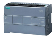
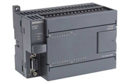
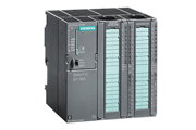
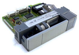
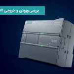
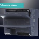
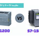
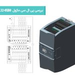
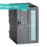
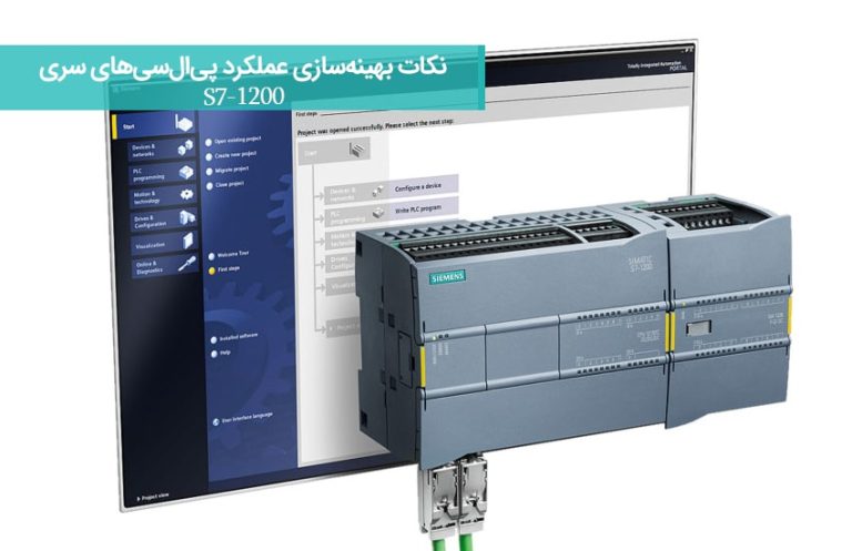
In the training, we intend to give a general introduction about S7-1200 PLC along with CPU1212C and AC/DC/Relay modules and its inputs/outputs. The content is as follows:
- PLC hardware concept
- How does the processor work?
- How to write I/O
- Conclusion
Well, as you know, we are using an S7-1200 PLC that is placed on the table and turned on for this tutorial.
The first part of the concept of PLC hardware:
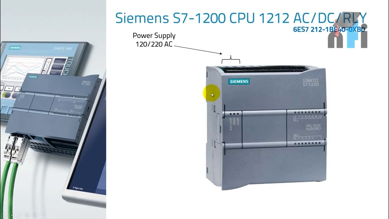
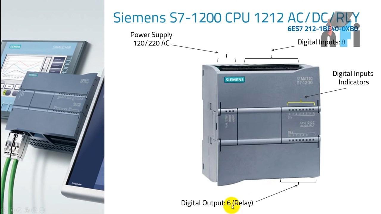
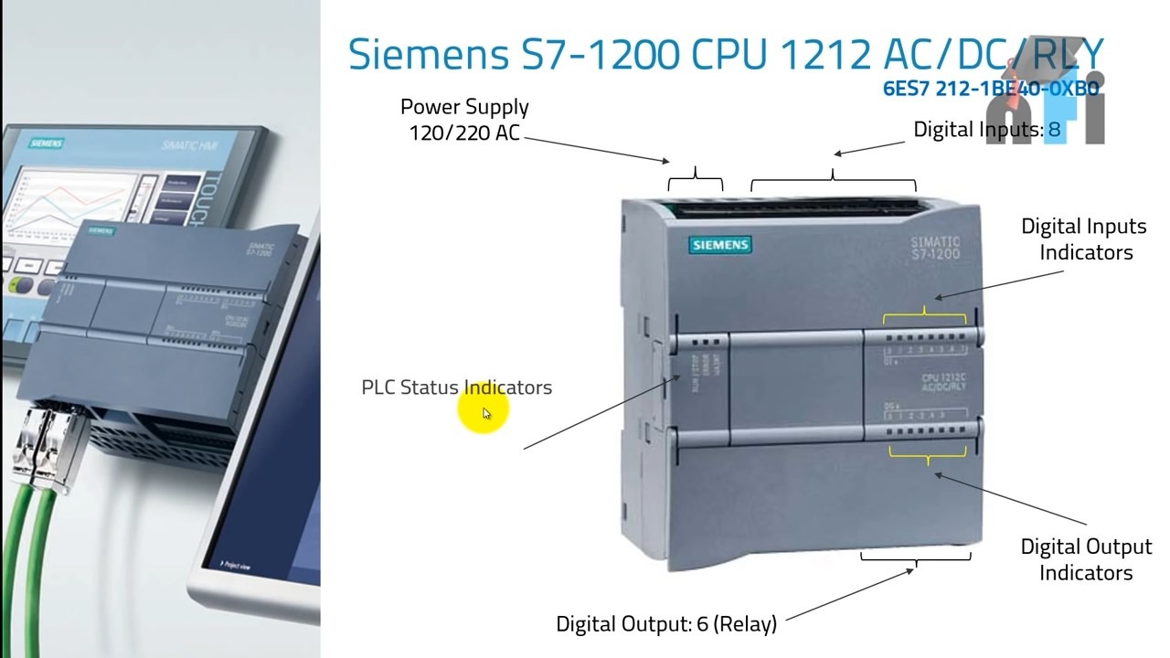
The first part of interest in the PLC S7-1200 is the power supply, which must be powered by a 220 or 120V power supply. You may find PLCs that are powered by 24V, but this model is powered by AC input voltage . There is no problem and this case is precisely because of having power and the same internal power supply. which is shown in the picture.
This section exactly converts AC current to DC and you no longer need to use a separate power supply.
Digital input:
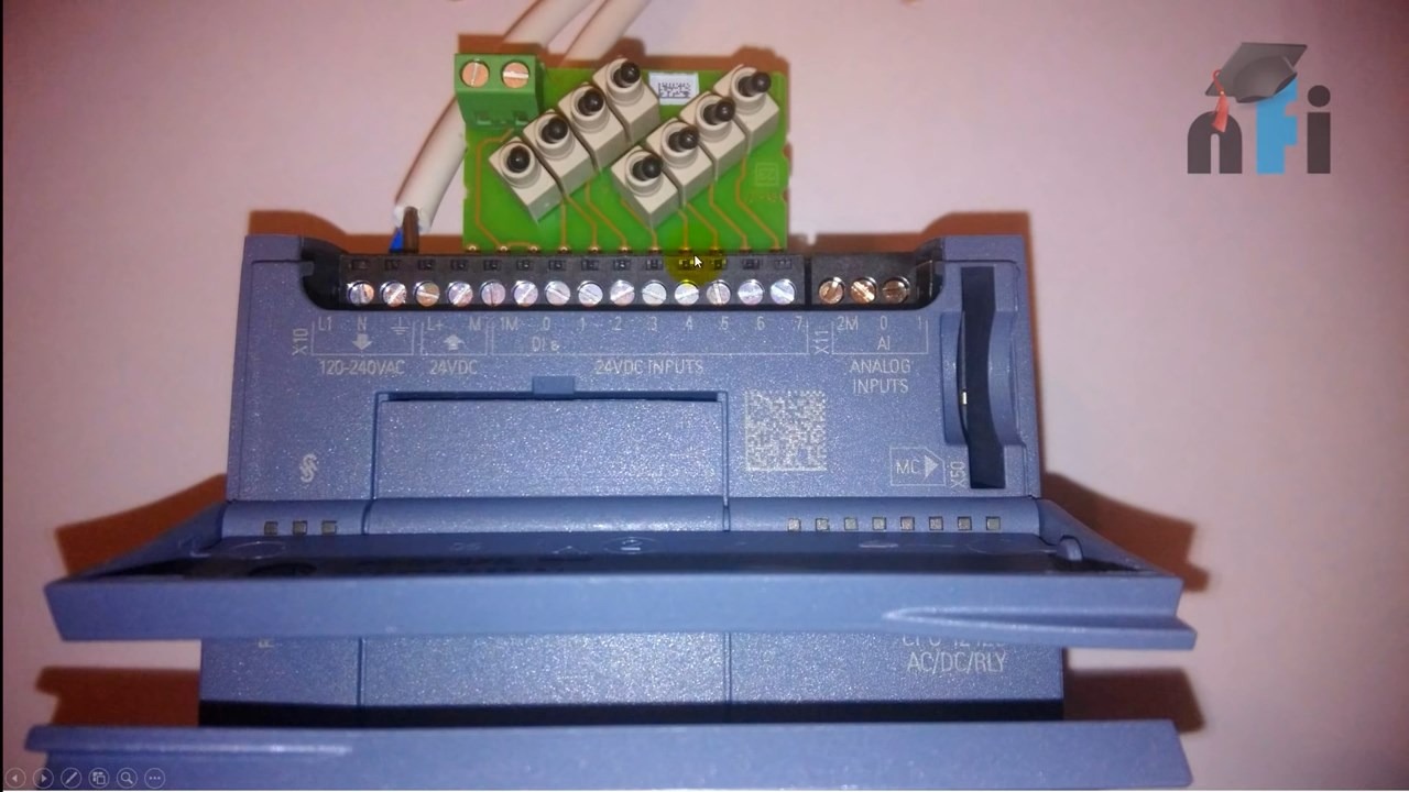
The next part that is discussed is the digital input, which receives the input signals and processes and outputs them through the PLC. As you can see from the PLC, this part has indicators on the PLC body that are exactly It shows how many inputs we have (in this case there are 8 inputs), each of which indicates whether it is off or on with its indicator light. Generally, the green light state indicates that the input is on and the dark state of the light indicates that the input is off. You can also see from the photos that when we are connected to the inputs by an input simulator, and by turning on the input, it turns on exactly on the PLC , even if we activate another switch, its indicator light is added and turned on. .
Digital output:
Well, the next part is the digital output, whose representatives tell us that we have six types of relay outputs. In fact, we have two types of PLC outputs.
- A type of transistor
- Another type of relay
The output of the relay type has more current and more current capability.
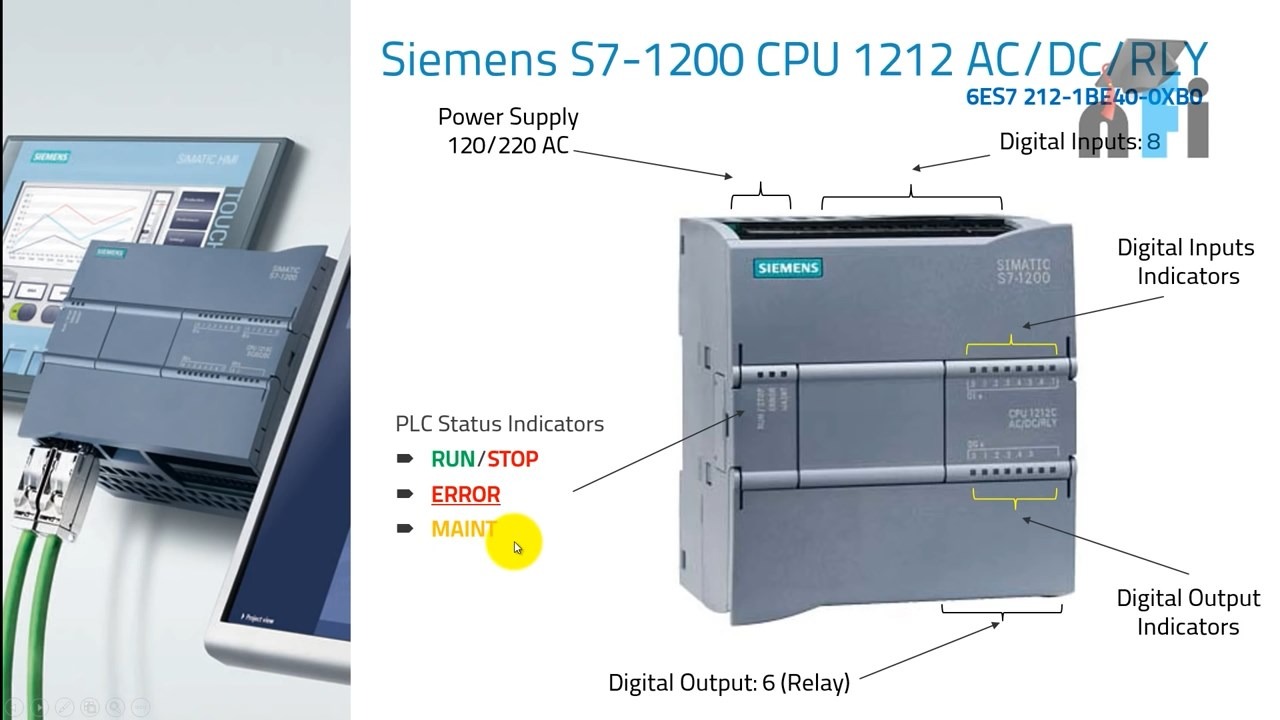
So, we found out that both the outputs and the inputs have indicator lights. We also have some other non-indicator lights, so what are the characteristics of these lights? In fact, these LED lights report the status of the device. The three main lights in PLC S7-1200 are as follows.
- The indicator light shows the status of running and stopping the PLC
- Error indicator light
- Maintenance light
The first light shows that the PLC is in a logical execution state and gives you an output. The error and repair and maintenance lights show error messages and take the device to repair and maintenance mode respectively.
Checking the input terminal:
The first part from the left, which is L1 and N and has a downward arrow, is for the power supply part, which is indicated to be 120V and 220V AC, and the number on the side is a special number for these three terminals. The next part Or, the next two terminals are L+ and M, which have an arrow pointing upwards, which means that they are DC output, which takes 24 volts DC from this device. The next part, which has 8 terminals, is for connecting your digital input. has been specified and finally we have the analog inputs, one of which is 0 and the other is 1.
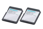
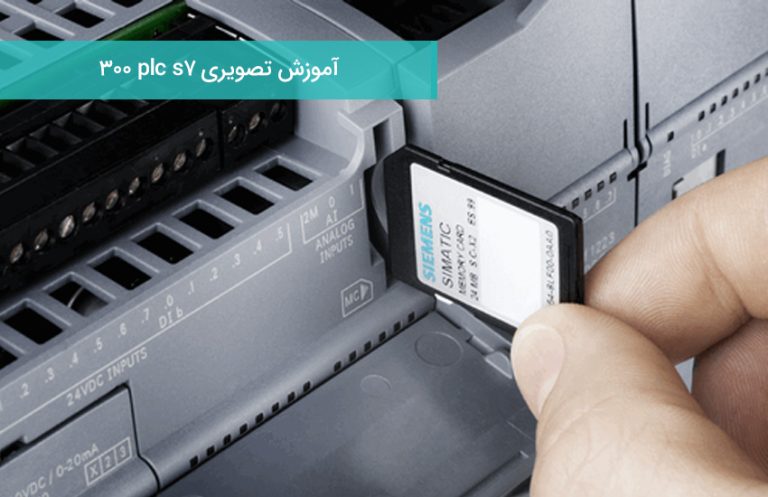
The next and side part is the memory card section that stores your program information and the PLC can read the stored values for you from the memory card.
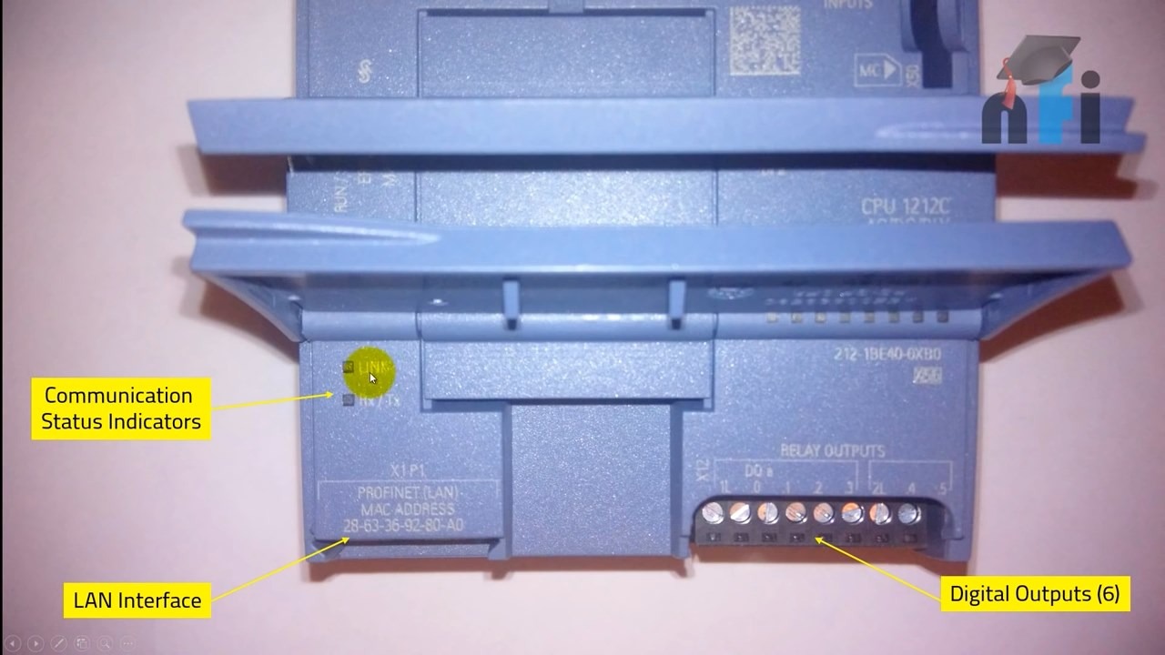
Outputs: As you can see, this part is the output terminals of PLC S7-1200 .
From the left side of the first section, we have the lights representing the communication status, which are LINK, RX and TX status. If your PLC is connected to a Siemens HMI or another device that uses RS- 485 or Ethernet standard . supports, this LED will show you the status of the connections, whether the communication is good or not. Then you have the internal network (LAN) interface, which is one of the most important features of the S7-1200 PLC. You will no longer need a Siemens S7 or Micro Logic 1000 programming cable. With this important and practical standard, you can easily program your PLC via LAN. The bottom part is the MAC address or the physical address of your LAN.
The next part is the relay outputs , as we mentioned earlier, its terminal in PLC S7-1200 has 6 outputs.


